Base plate connections are used as support for columns coming off a concrete pad or foundation ensuring longevity and stability. When installing, it is essential to leave a gap of around 20 – 30 mm between the concrete and the steel plate, which can be achieved using shims and wedges. This gap will then need to be filled by packing a dry mixture of concrete, also known as a dry-pack, into the gap.
Connections
Steel connections are vital components in construction and engineering. They are available in diverse forms and are categorized based on their design characteristics. Gaining knowledge of the various steel connections and their properties is key to choosing the right connections for your project.
Base Plate

End Plate
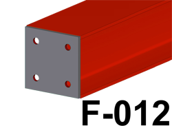
A steel end plate is a flat, typically rectangular, metal piece fixed to the end of structural beams or columns. It features pre-drilled holes for bolts to pass through, facilitating secure connections with other structural elements.
This straightforward and robust component is vital for ensuring a structure’s strength and stability.
End Plate Connection
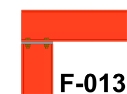
End plate connections are a method used in structural engineering to join beams or columns. It involves affixing an end plate, to the end of a structural member. Aligning pre-drilled holes and connecting bolts through the holes ensuring a secure connection.
This technique is favoured for its sturdiness, simplicity, and adaptability in various structural configurations.
Moment Connection
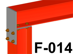
Moment connections feature overhanging plates that bolt into a column. This type of connection is frequently used when the connection needs to withstand a high ‘moment’, for example, if a wall is replaced with a box frame that will need to withstand high wind loads from the sides.
Cleat
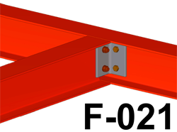
A cleat is used to bolt one beam into the side of another beam. Cleats are made from RSA sections (angles), which are then bolted to both beams. In cases where only one side needs bolting, only one cleat will be required, and for some projects, it is preferable to weld the cleats to the end of a beam rather than using bolted connections.
Spacer - Beam
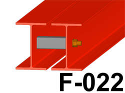
When projects are struggling for height, for instance in basements and lofts, it is often preferable to replace a deep beam with two smaller beams. However, to ensure stability and resistance to buckling, these beams need to be bolted together, and this is where a spacer is used and is usually welded to one of the beams. The bolts are typically 600 mm apart from each other.
Spacer - PFC
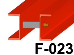
When a cavity wall needs to be supported above an opening, two PFCs can be bolted together back to back, with a spacer inbetween, in order to give strength to the walls. The gap between the sections matches the width of the cavity, and the spacing between the bolts is 600 mm from centre to centre.
Crank 90°

A 90° crank is a typical crank but with two kinks. In a 90° crank the top member will be horizontal and the bottom vertical. Cranked beams are most frequently used to support roof structures, therefore the angle of the middle member needs to follow the pitch of the roof. It is crucial that full penetration welds are used with these connections to ensure the crank will carry the load.
Kink 90°

90° kink connections have two steel sections joined by a weld. It is used for brackets, or for when a beam needs to be supported by a column and a bolted connection cannot be used.
Kink – angle

With some projects, a single kink that follows the pitch of the roof is adequate for the support required, and the end of the beam is supported without the need for an additional vertical column.
Kink with plate

This is essentially a ‘kink–angle’, but with an additional plate between the two sections. This type of connection is used when the two pieces being joined are of different sizes.
Gusset
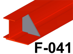
A gusset uses a plate, which is normally triangular and is used to provide additional stiffness to the structure. It is often used to support the outer edge of a bottom plate welded to a beam.
Plate – bottom
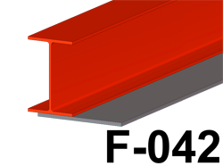
A bottom plate is added to a beam in order to support brickwork or timber joists. The bottom plate is stitch welded to the beam and is often offset to one side so that the brickwork is sufficiently supported.
Plate – top
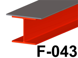
A top plate is added when the size of the required beam is smaller than the wall it is carrying. An example is a door opening in a cavity wall.
Stiffener

As the name suggests, a stiffener provides additional stability by connecting both flanges and the web. This prevents the web from buckling.
Tab
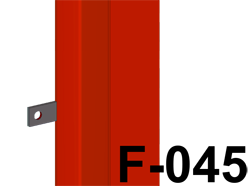
Tabs are welded to hollow column sections to make it possible to anchor them to walls. In most cases, M12 anchors are used every 600 mm and in a staggered formation.
Hole – flange
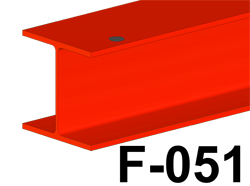
Holes are drilled in column flanges, either UC, UB or PFC, in order to anchor them to walls and as an alternative to welding tabs. In most cases, M12 anchors are used every 600 mm and in a staggered formation.
Hole – web

Holes are drilled in the web of the beam to enable timber joists to be fixed to both sides. Timber joist hangers are then fixed to the beam joists, allowing floor joists to be spanned from them.
Splice A1
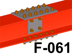
Splices are required when a beam is either too long or too heavy to install safely. When a beam spans two party walls, a splice is also recommended to easily install the beam, with the alternative being temporarily removing a large wall section. As a rule of thumb, the flange plates need to be at least the same thickness as the beam’s flange and the same rule applies to the web plates.
Splice A2
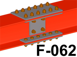
In some cases, the structural engineer may request additional inner flange plates for the splice connection.
Splice A3
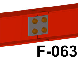
This type of splice is not a full-strength connection and therefore is only used to align two sections. This type of connection needs additional support, either via a column or by a padstone.
Splice B1
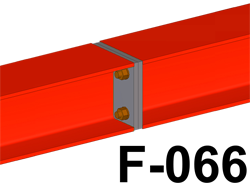
When height is limited, regular splices such as A1 and A2 can add as much as 100 mm to the total depth of the beam, therefore are not desirable options. In this case, you can consider using a B1 splice, although it is not a full splice and therefore will be unsuitable for some applications.
Gallow Bracket
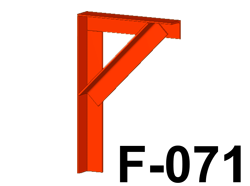
Gallow brackets have been used to support chimney breasts for many years, however many local authorities no longer allow them to be used. If your planning department advises these are not allowed then you will need to use a full steel beam structure instead.


